sâmbătă, 27 iulie 2013

Finished Brawa Platform

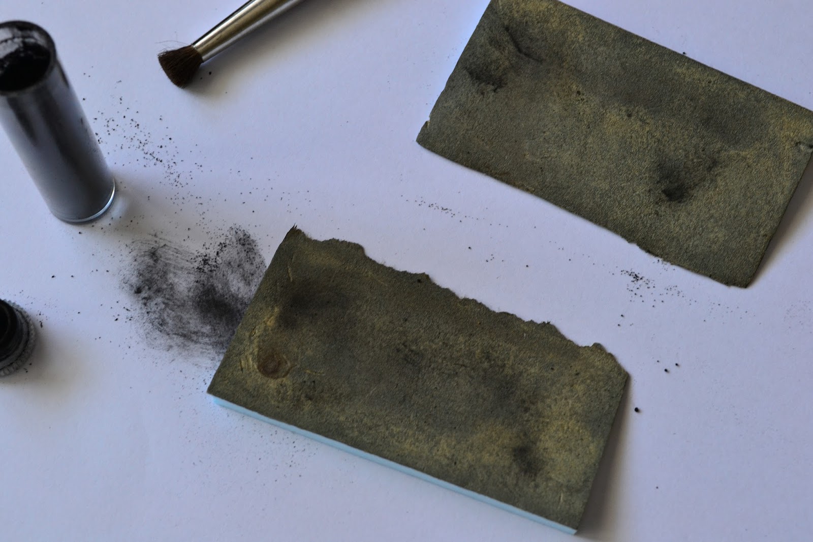
First described here, the Brawa platform is now almost completed - first 2 photos show the status captured minutes ago. The asphalt cracks are partially filled with some winter miniNatur static grass, probably some autumn model will be added too.For asphalt, a hard foam was used (photo 3) - this has been originally used to package the Noch tunnel lining and came quite handy now. Various cracks and dents were applied, to simulate as closely the real surface. The color was obtained as follows: first, all was painted with Woodland Scenics (WS) Stone Gray; after this dried a series of washes was applied, only after the previous one completely dried, in order: 1:8 WS Concrete, 1:8 WS Burnt Umber, 1:8 WS Yellow Ochre, 1:3 WS Stone Gray (as opposed to the rest, this was applied perpendicular to the length of the platform), 1:8 WS Yellow Ochre. After the first yellow wash, some Noch black weathering powder was used to break the monotony - even if this looked too powerful at first, the subsequent washes toned it down just right.
After painting, the soldering gun was used (photo 4) to take away from the edge, so that it will bind correctly with the platform edge which was already fixed. The groove of the thermocutter was used to hold the foam in place. 2 supports were made from regular foam in order to support the platform once fixed (photo 5), after which it was glued, with the same Woodland Scenics color containers that were previously used for washes pressing down (photo 6). The angled platform ends were painted in the same way, then fixed.


Hints


Over the time, I've been compiling quite a list of small notes, consisting of small hints and some activities that should eventually make it to the plans for each section of the model railway. Since every time I run into the pile I keep reading the same things - I've decided it's time to put the hints somewhere, and the activities to their respective plans. Hints are centralized below.

 1) When unmounting a point switch, it's more easier to simply gently lift the tile where the motor rod connects (2nd photo) - like this there's no need to go underneath and unscrew the "cheese" screw that clamps the rod to the point motor mechanism. If not doing this too often, the hole in the plastic tie shouldn't get larger in time
2) The plaster cloth "lids" should have a non-uniform contour, so one cannot easily spot the difference in height
3) To provide access to various wires underneath the terrain, buildings with removable roofs can be placed on that spot
4) A landmark for plaster cloth "lids" can be achieved by gluing specific plants on the terrain supporting it, so when the lid must be placed on the layout, there's no doubt about its final position
 5) The Noch glue, used for the static grass, is diluted 1:2 glue to water, so the there's no visible difference in the terrain color after this dries, especially at the "border" zone between the original terrain and the one that was soaked
6) The static grass should be pressed down lightly next to a figurine or on paths where there's supposed to be traffic
7) On areas where a plaster cloth "lid" will be applied next to a segment of track, there should be a minimum of 3-4 cm sideways from the foam support underneath the track - this will allow the edge of the lid to sit over the terrain, but not to close to the track itself (where ballast usually lies - making "hiding" difficult)

8) For the switch connecting segments D with C/SR, the "cheese" screw can be accessed with a long screwdriver, as seen

in the 3rd photo
9) For the same switch, removing the Tilling 86112 can be done using a mirror, placed like in the 4th photo, and using a curved screwdriver for the 2 screws holding it in place
10) The mobile rod for a switch motor can be easily removed if the point is brought into a "half-switched" position - this can be easily achieved by turning off the power for the switch motor, modifying the Phidget controller, then powering on briefly so the motor doesn't do the complete lap

marți, 23 iulie 2013

Artitec Oil Cart

Got a new order last month from LokShop that also contained an Artitec oil cart. Looks like Artitec is suggesting 2 color schemes - one with a bright orange for the barrel, the other, more natural, sporting a grey mettalic finish - as seen here. I opted for the latter. First photo is the small original package. Same as with the Artitec lantern building, the burrs need to be removed, this time using a combination of file and cutter. The second one shows the elements to be painted black - the chassy, supporting brackets, the wheel axle and the already masked (with 3M Vinyl Tape 471+) barrel. Last photo shows the progress over the parts to be painted in a wooden color - Tamiya Desert Yellow (XF-59) was used in 3 layers. Next up will be the piece that resembles a set of small oil canisters, located in the back of the cart itself, and finally the metallic parts - the barrel and the metal band on the wheels. Finally drybrushing along with some weathering will be used to finish it.


sâmbătă, 8 iunie 2013

Switch Issues

Soon after fixing the problem described here, I was worried that the same issue happened to one of the switches in the PT pair (M31), which experienced the same symptoms of poor electrical connectivity when part of the locomotive wheels were in the frog. Turns out it was only the Tillig 86112's brown wire that came loose from its connection with one of the wires providing power. When this happens, the voltage measured between any point of the frog and its opposing rail will be at about 6-7 Volts.
With this out of the way, I turned my attention to the switch in front of the tunnel, which started making a powerful noise for quite some time now. Opening the switch, cleaning it with the airbrush (blowing just air) and removing part of the components indicated that the motor was not at fault, and the cause of the noise was actually a broken cog - the hairline crack is visible in the first photo - not something that bad, but big enough to make the gap between those 2 teeth generate a considerable noise when being driven by the motor's worm drive. The whole component is present in figure 2. Luckily some time ago I've ordered a spare 86112, so the fastest way to fix the problem was simply switching the whole rod that contained the broken cog. Comparing the 2 switches (photo 3) showed no visible difference in this, but contrary to my memory, it's not just the color that was different among the first switch drives I bought and the subsequent ones - actually the motor itself is changed, and comparing the sounds one can immediately notice that the new ones are far more quieter. After everything was reassembled on the old drive and small amounts of silicone grease applied, I've placed the old rod and the components of the new drive (that interact with the rod) in one of those dynamic-compartment types of small plastic boxes, one of which I bought today.


duminică, 2 iunie 2013

Electrical Observations

Got curious today about how much current is being drawn by the whole layout, so I've made a quick measurement and noticed a rather high consumption: about 400 mAmps with one light signal, the Viessmann pickax figurine and the Brawa V100 idling.
I went ahead and opened the box seen in the photo to try and see what wire goes where. Since 2 sets of wires were connected using the thing which can be seen next to the measurement device's black connector, I decided to switch to using the Viessmann devices specifically built for this (the yellow one in the center with its adjoining connectors). This way the wires could be disentangled and tags were placed on each fire or pair of wires, depending on the case. Now with the ability to disconnect/connect everything one by one, the results became clear:
- LZV100 draws 160 mAps, with or without the output to the lines connected (rather important, since in the beginning I though there maybe were losses on the rails themselves, even though feeder wires are soldered to each rail segment) - in the photo this is the black box in the lower left corner of the cardboard box
- the LK200 inverter didn't consume anything (no locomotive was ran on its segment though) - in the photo it's the small white device on top of the LZV100
- Viessmann 5223, the module that commands the 4013 Viessmann light-signal, consumes 80 mAmps
- the 4013 light signal consumes 20 mAmps (this includes its entries connected in cascade to the Phidget for obtaining the multiple aspects this signal is capable of)
- the pickax Viessmann figurine draws 30 mAmps
- Brawa V100 consumes 40 mAmps while in standby, 20 mAmps for the lights and 150 mAmps for the sound (when the sound effects aren't that noisy the value seems to go down)

Fixing Electrical Connectivity on the Long LR Switch

There have been some electrical problems for some time now, with the Brawa V100 going through this long switch, whose installation was covered here. When the locomotive would be going slow, in the position marked by the two red pins, it will lose power. Using an electrical measuring tool soon showed that the frog rails weren't receiving any power (the frog rails are the fixed rails that go "out" of the frog).
Fixing it would have been possible using Tillig's 85506 contact clips, but as with the rail joiners, electrical conductivity isn't that reliable. Only thing that would make sure the original issue goes away was soldering a wire to the frog rails.
Un-mounting the switch however wasn't that easy, since the rail joiners only slided completely at the upper end (by pushing the ties a bit; even if secured to the foam, the latter allowed just enough movement). For the other 2 ends -since 2 isolating Tillig joiners are used for the 2 frog rails, the rails had to be physically lifted to allow removal. Alcohol was used, using a pipette so that the drops could reach between the ties. After a few applications and a couple more minutes, the ties came loose and the switch lifted from its support.
In the second photo the cause of the problems can be seen: the metal piece joining both the frog rails (now soldered to the red wire) and rails inside the frog itself (now soldered to the brown wire; also it's clearly visible where these end, before the point blades themselves start) was secured in a faulty manner when this switch was build - resulting in poor connectivity. Cleaning of the metal spots and the soldering itself was done as mentioned in the article at the beginning. Even though the original problem consisted of the frog rails lacking electrical connectivity, I went ahead and soldered a wire to the frog itself, so this all this removal operation won't be needed in the future. Even if first decided to remove the violet wire soldered to the metal piece, I re-soldered it thinking that there's no harm in an extra point of contact.
All 3 wires were connected to the Tillig's 86112 white wire. The third photo shows how the switch looks like installed in its place. Some ballast must be glued so that the remaining holes can be hidden, and also some weathering powders to make the soldered wires invisible

The way the wires are connected together under the board is presented below for future reference:
I - blue, green, green, violet (the latter is the wire secured to blade associated with the inner route)
II - brown, yellow, yellow, blue(the latter is the wire secured to the blade associated with the outer route)

The rod connecting to sliding tie to the Tillig motor was cut to size also. One important warning is to secure the screw holding the rod, otherwise symptoms like the ones mentioned here can appear.


A very good guide for assembling the Tillig switch kits can be found here.

duminică, 12 mai 2013

Lantern Building Assembled

I finally got everything assembled. Some UHU super-glue was used the most, with some Bison special formula to get the roof attached. 

For the lamp, Tamiya Cockpit Green (XF71) was used as Artitec's LGN specification, while the door was airbrushed with Tamiya Red Brown (XF64), followed by a drybrush with concrete. Both items had Tamiya Flat White (XF2) applied where needed. For the 2 pipes belonging to the roof, the same gray used at the end of this previous article was selected.


Proxxon Thermocut

About 2 months ago, while trying to cut some thin layer of foam to be placed under the Brawa platform support, I realized that the same old ways I used to cut foam are making me lose hours, with the results never being exact. So I went online and ordered from a local online dealer the Proxxon Thermocut 230/E.

Priced at 130 euros, this machinery could have easily saved me days (!) of work back when I was building the ramps and various pillars. With a very thin wire that's kept straight by the arm, you can do cuts in various angles, both horizontally and vertically  (the piece holding the wire on the upper side of the arm can slide). The guiding system is really good and sturdy (maybe it has something to do with the fact that the machine is built in Germany). To be on the safe side, I ordered a spare wire coil (like the one seen here on the top of the arm) which holds 30 m of wire. The heating temperature can be easily modified and the base is actually printed with cm markings and a protractor - all in all one of the best investments recently made.

Lantern Building Roof

With my eye both on the finished building, as it appears on the Artitec site, and on the list of colours supplied by the same manufacturer, I first tried using something different for the roof than the colour recommendation dictated. Since Artitec used a copper-ish finish, and since I already had 2 small bottles of Tamiya XF-6 (Copper) I first used the formula below:

64 drops of XF-2 (Tamiya Flat White)
20 drops of XF-6 (Tamiya Copper)
87 drops of X-20A (Tamiya Thinner)


The result above wasn't really what I was after - the glossy effect actually ruined everything. Hence I turned to the suggested Artitec colours, bought the Tamiya XF-56 (Mettalic Grey) which is the corresponding color from Tamiya for the suggested Artitec list (they only give Revell and Humbrol colour codes) and used it, while trying to leave a hint of the previous coats. Below the result, after the roof was secured to the rest of the building.


Formula used the last time:


20 drops of XF-2 (Tamiya Flat White)
20 drops of XF-56 (Tamiya Metallic Gray)
40 drops of X-20A (Tamiya Thinner)

[later edit] This is the color ZK on the Artitec instructions

duminică, 21 aprilie 2013

Both Edges Completed on Lantern Building

After trying to find out just the right mix for the Artitec suggested colors - namely their Cement (CE) and Blue Green (BG), I finally got the paint sprayed using the airbrush on most of the building's faces, while using a no 1 brush for the drain pipes. Formulas are listed below (CE is on the upper side on the wall, BG on the bottom one) - note that the previous color used has now been switched.

CE (cement)
30 drops of XF-2 (Tamiya Flat White)
6 drops of XF-79 (Tamiya Linoleum Deck Brown)
2 drops of XF-1 (Tamiya Flat Black)

BG (blue green)
30 drops of XF-2 (Tamiya Flat White)
2 drops of XF-79 (Tamiya Linoleum Deck Brown)
2 drops of XF-1 (Tamiya Flat Black)


luni, 15 aprilie 2013

Upper Wall Edge of Lantern Building

For the upper edge of the building's walls, the Artitec instruction paper indicates using a mix of white (more), a shade of brown (Humbrol 110 - small amount) and black (small amount). This is referred to as cement in the said flyer. So a small quantity of paint was mixed, as follows:

30 drops of XF-2 (Tamiya Flat White)
2 drops of XF-79 (Tamiya Linoleum Deck Brown)
2 drops of XF-1 (Tamiya Flat Black)


The result, representing just one wall barely sprayed in 3 coats, along with the pieces of various types of masking tapes, can be seen below.


[Later Edit] This was replaced as indicated here.

luni, 1 aprilie 2013

Lantern Building Walls

One side of the lantern building had its wall airbrushed tonight. The texture of the model is really good, and using the airbrush really shows the details - an ordinary job using a brush will most likely make all the details fade. Care had to be taken though with the specs of dust, that tend to stick to the surface after spraying a coat. However I've done one mistake: the center of the windows should have been covered as well, because a thin mist deposited on the window sides on the inside. However with the white windows applied, this might not look too bad after all, providing a bit of a "highlight", usually needed for the small models because the light doesn't cast the same shadows compared to the real thing (so say the experts).
 The formula used, applied in 3 coats, follows:
0,9 ml XF-2 (Tamiya Flat White)
 6 drops of XF-64 (Tamiya Red Brown)
 1 ml X-20A (Tamiya Thinner)

The 3M masking tape applied on the bricks had the added benefit of removing extra mortar that was lying on the face of the bricks themselves.
T

duminică, 31 martie 2013

Bricks on the Artitec Building

While looking around the Internet for tips about using masking tape, I've come across some very interesting advice: the normal masking tape, the light-colored one, that when looked up close seems to have all sorts of ridges, is actually not the way to go for miniature painting. The trouble with this - even excellent for use on regular house work - is that it's too thick, making the paint sprayed from the airbrush to accumulate on the edges. Also, even if one tries to really level it, it usually bleeds paint. Enter the 3M vinyl masking tape, which solves these issues, and above all, it's not that sticky, plus the vinyl can be maneuvered a bit to take the desired shape. Somewhat pricy, at 15 euros you can get this as a 6 mm wide by 30 metres long strip.

 After carefully masking one side of the building, so that only the brick parts were visible, paint was prepared:
 0,6 ml XF-7 (Tamiya Flat Red)
 0,1 ml XF-64 (Tamiya Red Brown)
 0,7 ml X-20A (Tamiya Thinner)

This was airbrushed in 3 coats, using a lamp to help dry the paint between the sessions for 10 to 15 minutes. After everything dried overnight the mortar lines were done - first using a dry cloth with Woodland Scenics Concrete to cover the whole brick surface (this needs to be in sufficient quantity, since it will be left for about 10 minutes to dry - when this happens the paint tends to recede from the lines between the bricks; if this happens, another layer should be applied using the cloth soaked in Concrete color). After this has been left to dry for 10 - 15 minutes, a damp cloth can be used to remove the dried color from the bricks' face.

Even if the mortar might not be removed 100% from the bricks themselves, not to worry, since the Artitec guys seem to be having a similar finish on their product cover. As for the brick color, this was chosen so that it matches that of the Brawa platform detailed back here

duminică, 24 martie 2013

Artitec Kits

It's been a while since I first noticed the Artitec kits in the offers of various model shops. Pictures of the complete models really looked awesome, by far the most realistic among the rest of the crowd. Trouble was the usual online retailer I'm using - LokShop - doesn't offer any Artitec products. But since I had my eye on a small building that had just the right dimensions to fit on the D segment, and also they had a nice small ship (only the part above the water) that fits well in one of the layout's corners, I decided to go ahead and order directly from their site (http://hobbyworld.nl/). Due to a certain local holiday, the delivery was set back about 2 weeks, but finally arrived. Luckily for me, I found out a couple of months ago that the Artitec kits come unpainted, so that awesome picture of the desired model is really up to you. 
So I went ahead and started working on the Lantern Building (#10228). Don't assume you'll be dealing with state-of-the-art, laser-cut materials. Actually it's a really good opportunity to see how models evolved over the years. Compared to the Faller station I got  last year, this has its issues. First of all, the "Copyright 2005" gives the fist clue. Then you're greeted by resin parts, all having a pretty thick film on the back, which needs to be sanded away. The second photo shows my first attempt at it, however I had to go and buy some real sandpaper to get the work done. In the end it took more than 2 hours total time to only get the parts separated...and a lot of messy plastic dust on the way.

duminică, 17 februarie 2013

Tips and Progress

Finally decided to use diluted glue when applying the earth plaster formulas - the trouble was that for the very first layer applied on the wet (previously dried) plaster cloth, after the time needed to dry, most of it would simply come off - most likely as a result of the underlying plaster cloth robing the moisture from the small plaster particles in the earth formula. So in order to "help" the reaction of these small plaster particles with the mist airbrushed, I'm switching from simply water to white glue (1 part glue to 2 parts water). However thinking a bit further makes me realize that when vegetation get applied in the end, the underlying soil will be fixed anyway by the diluted Noch glue used specifically for the static fibers - guess my changed procedure will just help in those barren patches of land, left between vegetation.

Regarding the Noch glue used for the static grass, I've changed the ratio to 1:2 (Noch glue : water). This is done in order to reduce the visible change in color after the glue dries versus the initial color of the vegetation. (Kept reading a small note with the new ratio for some months now, so I decide it's finally time to write it here too).

The right corner that has seen much work last December now has some small rocks and dead, fallen trunks applied (using normal glue - white glue didn't work !). Since the first photo was taken, patches of various grass were set. As for the second photo, the lids can be clearly seen, still awaiting to dry. In the foreground, the Brawa platform is glued in place to the 4 mm supports (which took way to long to cut using hot wire). Also visible is the remaining infrared detector pair that had to be installed on the D segment, right before things were fixed with some plaster.


sâmbătă, 16 februarie 2013

Brawa Platform


On the D segment, it's planned for a platform to show up. First photo shows the place - on the right of the track. I've bought one a while back, but as these things come with the natural plastic gloss, processing was in order. First, the grey parts were filed, so they wouldn't be smooth - this to confer some grip for the upcoming airbrush coats, and for some surface variety on the drybrushing step.For the bricks, 2 layers were used, in the formulas presented below:

First layer
 0,6 ml XF-7 (Flat Red)
 0,25 ml XF-64 (Red Brown)
 0,8 ml X-20A (Thinner)

Second layer
 0,3 ml XF-7
 0,05 ml red brown
 ? ml X-20A (Thinner) (quantity was most likely 0,4)

After this, the mortar lines inside the bricks were done, using some cloth soaked with Woodland Scenics Concrete. This was gently wiped right after with some wet cloth, to remove the color from the bricks themselves.
The rest of the grey stones were sprayed in a combination of XF-12 (J.N. Grey) and XF-79 (Linoleum Deck Brown) - unfortunately I don't have the exact formula anymore - judging by the end result however, a small amount of brown was used.

Next, drybrushing was done, on both bricks and stones, with various Woodland Scenics colors (Burnt Umber, Raw Umber). The rough edges on the grey stones were highlighted using WS Concrete. The final assembled piece looks pretty good for now.


duminică, 3 februarie 2013

New Rock Painting Formula

Some time ago I've painted the 3 rocks on the corner of the LR segment, visible on the aerial shot on the bottom right. Since then earth has been added, along with some ballast (however this is not yet glued). Going through my small notes I've found the recipe for the 3 rocks, which I'm pasting below:
- 1 wash of WS Yellow Ochre (1:4 color:water), specifically on the sharp edges
- 1 wash of WS Burnt Umber (1:4), on the rest of the surfaces
- 1 wash of WS Black (1:16)
- 1 wash of Burnt Umber (1:4)
- 1 wash Black (1:8)

Obviously some steps can be consolidated, however this was the initial method used. Pictures follow - click for a higher resolution pic.

duminică, 13 ianuarie 2013

The Aerial Shot

  Never really got round to actually uploading the plan of the layout, so today I've taken 2 photos using a tripod, high enough so that the Nikon was touching the ceiling. Next the 2 photos were merged as seen here.
  The progress can be clearly seen on this one - only that in the last few hours the white area to the right was covered in earth, yet this needs to be redone in certain places, since the plaster didn't quite stick.