After switching the hand and sheets of paper with actual rolling stock, troubles started with the optical sensors. The Phidget 1018 and its IR detectors just didn't perform as expected.The problem with the infrared detectors was that the board they were installed on was quite big, and it was difficult to hide this behind a tree or some bush. An apparently good thing was that the IR emitter and the detector were placed on different sides of the same board, so this meant I didn't have to have 2 detectors, in an across-the-track positioning. But after a few days the problems grew: the black plastic of some locos and cars were giving a hard time to the IR detectors, because - as I would later discover - black plastic materials absorb infrared radiation, and so the dark-colored rolling stock was invisible to the detectors. If this were not enough, it wasn't so easy to cover the board behind some form of a wall, with a gap small enough for the IR to flow, because the infrared would just bounce off the inner part of the wall, and back to the IR detector, giving a false reading. So the detection solution had to be rethinked.
I considered buying more powerfull Sharp detectors for a while, but then dropped the idea, since the price was rather high, and I couldn't rely on this reflective method 100%. Searching around the net, in december last year, I discovered Mr Matix, that produced optical detectors specifically designed for model 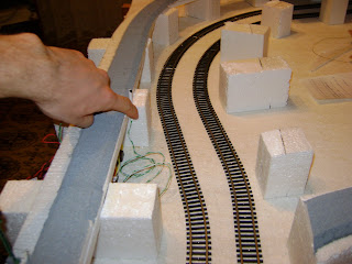 railroads. Basically for 15$, you got a separate IR emitter and a detector, and one board to hook these up. The good part was that this board could be connected directly to the Phidget 1018 input interface, instead of the IR Phidget sensors. Also installing the emitter and detector across-the-track, meant that there were no more issues with rolling stock material; if something was there, it would be sensed reliably, without false readings.
 railroads. Basically for 15$, you got a separate IR emitter and a detector, and one board to hook these up. The good part was that this board could be connected directly to the Phidget 1018 input interface, instead of the IR Phidget sensors. Also installing the emitter and detector across-the-track, meant that there were no more issues with rolling stock material; if something was there, it would be sensed reliably, without false readings.
 The photo on the side, took in april this year, shows the detector. I took this because I wanted to remember where it was positioned, since the detector was fixed using the tunnel ceiling.
With the detection problem solved, I went on to test the Phidget motor controller. With the DC operating mode, you actually command a segment of track; a voltage applied on this will move all the locos in that particular segment. Therefore you need to segment the track on the layout. This was already done, since PIKO produced little sections of track, that were gapped on both rails. So I connected 2 outputs of an Phidget 1060 to 2 neighbouring track segments. On a single segment everything went ok, but when the loco crossed the gap, it will get a sort of power surge, until it reached the other segment completely. Another issued appeared: the board itself used a pulse-width modulated signal, basically it was applying the maximum voltage on the loco for a fixed duration, then turning if off. For example, to get a 30% speed, 12V (the maximum voltage for DC operating mode) were applied for 30% of the time, then for the rest of 70%, the voltage was 0. This was of course repeated many times per second, so the effect would be smooth. There are however 2 known problems with applying this kind of signal to DC motors - first, the widespread idea that the motors would overheat, which I did not ran into, and secondly, the locos make a sort of buzzing sound. The buzzing was noticeable - imagine small birds singing quietly from within the loco, as the voltage increases - not very pleasant, but I could just go with this one. Another problem with the controller was soon experienced: the possible voltage was in the range -12V +12 V. For the positive side all went ok, but when you went from a negative value, to a smaller negative value (eg. from -10 to -9), the voltage would momentarily drop to 0, then get back to the correct value. Although it happened quite fast, it was noticeable, as the decellerating loco would appear to stall repeatedly. Yet another incovenient became apparent when the loco crossed the gap - sparks were produced, and this produced false readings in the optical detectors, in a random fashion. So the end of december saw different efforts to resolve the "gap" issues - various large inductors connected to the outputs of the Phidget controller, and a lot of documentation read for computing the correct value for this inductors. In the end the problem was that the controller outputs didn't have an internal common, so when the loco crossed the gap between 2 sections of track, each powered by a different output, in effect 2 different sources were connected together - something that in electronics is not recommended, because the resulting output isn't clearly determined.
Because the time invested in researching solutions for the various controller problems was getting out of hand - sometimes experimenting until late at night with various inductors and an oscilloscope - I decided that the Phidget 1060 had to be abandoned. Searches for direct current controllers weren't so successful, so I started researching DCC more closely. Now in DCC (digital command control) you no longer control sections of track. There's just one big continuos track, and the locomotives can be operated individually. You also get various goodies: output functions (light, whistles, bells), joining 2 or more locomotives in a consist, consistent lights on the locos, regardless of their speed (unlike DC, where the voltage applied to the track also imposed the lighting for the locos and inside of lit passenger cars) and a lot more. Only problem with DCC was the high price...
Niciun comentariu:
Trimiteți un comentariu