I've decided working on the SR segment for a while, postponing the completion of the rock test board. The next part to do here was to continue laying the track up to the switch that's already in place. After taking the ties strips that were already painted since several months ago and
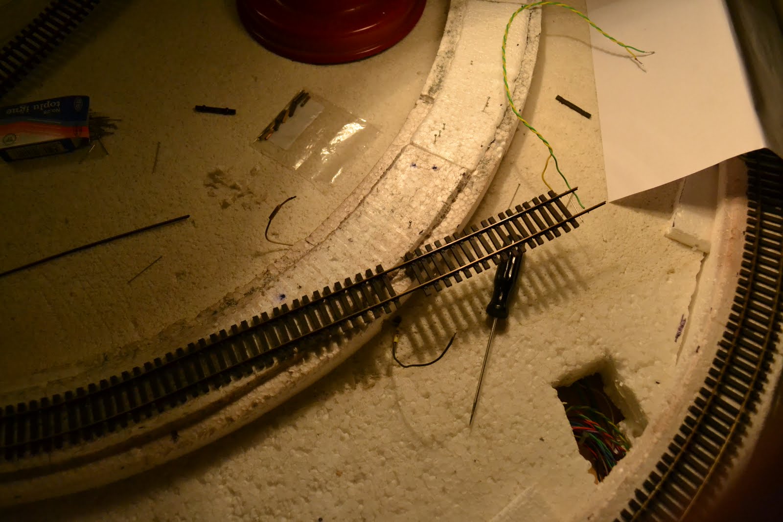
treating them with a combination of concrete dry brushing and raw umber / black washes, the Tillig rail profile was inserted and the track made ready for installation. Unfortunately when connecting this bit with the one already glued it quickly became apparent that i've run into a kink. What this means is that the curve is not smooth, causing it to "break" at the joint, because the end of the curved flex track has a tendency to straighen itself. To overcome this, 2 solutions are at hand: first, connect the pieces while straight, then solder them, so when the rail is bent, the curve will be natural, or the second one, stagger the joints, in other words making sure that the track is not sectioned in the same place so there is an offset between the cuts in the rail.
Since I'm not a big fan of soldering track segments together, opting instead for soldering feeders on each track segment (for electrical connectivity reasons), the only option was staggering the joints. Further analyzing the already laid in place track revealed the the curve's radius near the end was too sharp, causing derailments. So without rail templates (small metal gauge devices that you can slide through the track so one obtains the right radius) and with the 1:1 plans long since removed from the foam board, i had to resort to primitive measures: the center of the

curve for the start of SR was determined and a long crochet was inserted in the foam board, in that specific spot. Then using a ruler with a predefined small hole near its end, the correct radius could be obtained by using markings on the foam subroadbed. Next was determing the maximum distance for staggering the joints, since the 1m rail profile was supposed to last until the switch. This turned out to be 9 cm. A plan was then devised:
Step 1. Unglue the end of the glued track using alcohol and cut the outer rail by 8.6 cm; the cut had to be obtained by using 2 cuts back-to-back with the Xuron track tool, so the bit of rail could slide of the ties easily
Step 2. File the end of the rail, so the joiner can slide in smoothly
Step 3. Cut 2 ties in the place where the rail joiner will be
Step 4. Attach joiners at this end, then fix the whole track with pins and mark the places where the rail will be cut at the other end (near the switch)
Step 5. Cut the rails at the other end and then use a filer so the rail joiners will fit (a normal joiner and an isolated one for the rail connecting to the frog)
Step 6. Use a marker to draw signs on the foam roadbed to note the position of the curve (the foam roadbed was not attached yet at the moment when this plan was created, while the other pieces -the ones before the bridge - were already glued)
Step 7. Mark the places on the track where the feeders will be soldered (a permanent black marker works best for this)
In preparation of the soldering, this step was further expanded: for the new track - for the

switch side, the soldering points will be located after 1 free tie (the kind that are used at the en
d of a flex strip - they don't hold the rail together, as to permit the rail joiner to slide) and 7 normal ties; the points were to be marked on the side of the rail where the feeders will exit from the track; for the lower side, the points will be after 1 free tie + 4 normal ties; separate wires will have to be used because the rail will be curved afterward, causing one of the points to gain an offset to the other. For the old track, most of which was still glued, only a single soldering point will be needed and it will be located between the first and second ties next to the end of the outer rail; the first tie had to be eliminated (in its place, a free tie will be placed) and the second had to be moved by sliding on the inner track to ensure there was room to work.
The key to a good solder joint for a feeder is cleaning the metal spot on the back of the track. I use a bistoury with side-by-side and diagonal movements, so there is a small metal residue coming off, thus ensuring that all the oxide and various coatings on the metal are taken off. Take care as the spot needs to be only as large as necesarry, excessive cleaning of the metal leading to a large zone being covered with solder, and the ties will not fit on their original place. Next a small piece of flux is melted on this spot using the soldering iron. After this, the metal spot should have a thin solder covering, that looks shiny (usually the sign that it conducts electricity, as opposed to a cold solder joint, that will brake in time and that has a different look).

Then the feeder can be soldered, by heating it with the soldering iron against the back of the rail. The resulting joint should be mechanically solid and have the same "shiny" look.
Niciun comentariu:
Trimiteți un comentariu