From the last post, a couple of things happened: the order i was waiting for finally arrived (after being refused at the airport in Germany the first time because it contained a Noch fixing spray) and another order was received, containing amongst others the switches for the pre-tunnel segment and a couple of meters of Tillig Elite code 83 track. Both were from LokShop. Also I ordered the Xuron 2175B track cutters, since it seemed an invaluable tool for working with flex-track when reading what others were saying on the web. This came from Shesto in the UK, since LokShop did not have this in stock, and Amazon had this thing in stock only in the States, but they would not deliver it to my address.
I managed to build a crude form of foam cutter,  since the old one(s) (there were 2 of them) were somehow misplaced. The nichrome wire proves a real challenge to find around here, as I was only able to find some 1 mm thick wire, after searching through a dozen shops. Anyway, the photo on the left shows the first one, used for the roadbed on the SR (small ramp) segment. Pictured below is the SR segment (the small radius curve in the centre, and the outer one, barely visible, is the LR (large ramp) segment. The S/L naming comes from the radius of the curve, since the ramp of both segments is almost the same. The thing is all the roadbed and all the track was already mounted a couple of months back, but the roadbed had a couple of disadvantages: it was rather high, about 1 cm, compared to the Tillig roadbed, which is 0.5 cm, and secondly, the old track used to sit on top of the roadbed, including the ties; since the new
  track would have to have its ties embedded in the roadbed, the material used to coat it (saw-dust coloured grey, with the texture too small to simulate actual gravel) had to go. So right now about half the total layout roadbed has been stripped clean (using overnight soaking and washing away the sawdust), and the one needed for the SR segment in the photo is already cut to the correct thickness. Because of an initial slight error in mounting the wire, the roadbed also has an embakment, just like real railroads, where the track in curves is not flat, causing the train to slightly bend inwards and negotiate the curve better. A second wire-cutter was also built, for all the ramps that will be needed besides the existing ones - right now there is a need for the PT (pre-tunnel) segment and the link between the PT and the LR segments.
 since the old one(s) (there were 2 of them) were somehow misplaced. The nichrome wire proves a real challenge to find around here, as I was only able to find some 1 mm thick wire, after searching through a dozen shops. Anyway, the photo on the left shows the first one, used for the roadbed on the SR (small ramp) segment. Pictured below is the SR segment (the small radius curve in the centre, and the outer one, barely visible, is the LR (large ramp) segment. The S/L naming comes from the radius of the curve, since the ramp of both segments is almost the same. The thing is all the roadbed and all the track was already mounted a couple of months back, but the roadbed had a couple of disadvantages: it was rather high, about 1 cm, compared to the Tillig roadbed, which is 0.5 cm, and secondly, the old track used to sit on top of the roadbed, including the ties; since the new
  track would have to have its ties embedded in the roadbed, the material used to coat it (saw-dust coloured grey, with the texture too small to simulate actual gravel) had to go. So right now about half the total layout roadbed has been stripped clean (using overnight soaking and washing away the sawdust), and the one needed for the SR segment in the photo is already cut to the correct thickness. Because of an initial slight error in mounting the wire, the roadbed also has an embakment, just like real railroads, where the track in curves is not flat, causing the train to slightly bend inwards and negotiate the curve better. A second wire-cutter was also built, for all the ramps that will be needed besides the existing ones - right now there is a need for the PT (pre-tunnel) segment and the link between the PT and the LR segments.
The first switch and its motor were assembled back in June, using a small piece of plywood for holding everything together and trimmings on the f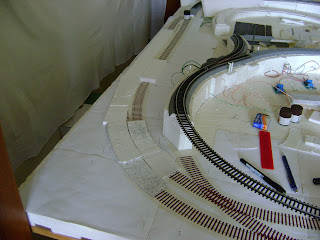 oam ramp to fix it in place. It hasn't been glued yet, and I'll upload some pics in a future post.
 oam ramp to fix it in place. It hasn't been glued yet, and I'll upload some pics in a future post.
Recently I started working on the PT segment. Actually the stuff in the last order was almost exclusively for this - 3 switches and some track and ties. I went for separated track / ties because it is cheaper and also I need to separate the ties for airbrushing. On the right photo the PT segment is the outer one, with pieces of foam ramp temporarily in place. The ramp dissapears just under the overpassing track, since the clearence is minimal. So the rest of the PT segment going to the right (the double track) will have to sit right on top of the big foam board, meaning the appearence of the roadbed will be an issue. Like this was not enough, I discovered that the Tillig switches wouldn't match the plans - it seemed the radius was larger than that on the plans. It seems this is fixed by mounting the switch in the cor responding ballast piece (which I was inspired enough to buy). But this means that I could no longer simply glue the track directly to the large foam board and pour the ballast above it, since the ballast piece goes a couple of milimeters beyond the ties' level. So the ballast piece has to be "submerged" a couple of mm. I first tried cutting precisely just the required area, so I could extract it and trim away those mm. Unfortunately there was no way to push it from underneath, since it was glued to the matrix of foam squares used to hold the big board in place. So the piece was hacked away using the soldering gun, new squares 1.3 mm thick were made, and a piece of 3cm thick foam board (upper right part of the right photo) was cut so it would form the underbase of the ballast piece for the first switch. Next is the mounting of the motor and see how it connects to the neighbouring track.
 responding ballast piece (which I was inspired enough to buy). But this means that I could no longer simply glue the track directly to the large foam board and pour the ballast above it, since the ballast piece goes a couple of milimeters beyond the ties' level. So the ballast piece has to be "submerged" a couple of mm. I first tried cutting precisely just the required area, so I could extract it and trim away those mm. Unfortunately there was no way to push it from underneath, since it was glued to the matrix of foam squares used to hold the big board in place. So the piece was hacked away using the soldering gun, new squares 1.3 mm thick were made, and a piece of 3cm thick foam board (upper right part of the right photo) was cut so it would form the underbase of the ballast piece for the first switch. Next is the mounting of the motor and see how it connects to the neighbouring track.
Niciun comentariu:
Trimiteți un comentariu