sâmbătă, 1 ianuarie 2011

Scenery Tests - How It Was Made

As promised, in this post I'll detail the steps taken to do the test board:
- first, I got a nice foam board, about 1 cm thick
- the flex track piece was cut to length, and the sleeper strips were sprayed in 3 coats as previously described here; the track was then assembled
- using the same railroad tie color as before, the track was sprayed from both sides, in two thin coats; no masking was necessary since no paint reached the visible area of the ties; this step is critical, since if left untreated, the already "pre-rusted" Tillig track would still shine and ruin every picture with light bouncing off the sides of the rails
- part of the foam board where vegetation was to be placed got painted with some brown (water-based "Oskar" pigment code 11); this is done to assure that if the next layer of "earth" placed on top doesn't cover everything, at least the white foam will not be visible through
- the earth texture was done inspired by Joe Fugate's article here (the magazine is free, it can be downloaded right there and i highly recommend it) - after the brown pigment dried, the area was airburshed using a mix of water and a couple of drops of liquid detergent, up to the point that everything is wet, but not as to form small poodles. The earth formula was then applied using a tea strainer (9.5 grames plaster, 0.5g burnt sienna, 2g orange and 0.3g black). Be sure to use dry pigment, not anything else (actually the brown water-based pigment was initially bought to try Joe's method, as at the time I wasn't aware that different kind of pigments existed, obviously the outcome of that experiment was pretty messy). The formula is applied just as long as the grains turn wet when they hit the board - no point to continue applying if they remain dried. After, I airburshed again the watery solution, somehow from above and horizontal, as to mist the whole area and to assure the plaster would bind. The zip texturing method is quite complex, eg by varrying the amount of water you can obtain a muddy look for the earth, so what i did first was to test different formulas on foam boards divided in small squares by using a crayon. I discovered that if not enough plaster is used, the color might be just right, but the whole thing would not adhere to the surface. So once again, check the article and do your own tests.
- a standard ballast foam piece was used to get the track to the correct height, and along with the track, was glued to the foam board
- Tillig dark ballast (86606) was applied on the track, and after it looked right, an eyedropper was used to soak everything using a combination of water and a few drops of liquid detergent - the liquid detergent has the role of breaking the surface tension, so that water seeps in nicely; after this, the whole procedure is repeated but using a water/glue mix with the ratio 3:1. I found out that when mixing the ballast glue formula, the best "cup" is a plastic bottle cap, since the amount of white glue is not that big. Joe Fugate goes into great detail explaining the method, and also Jon Grant has some nice photos of ballasting, also if you search for his posts you will find more detailed photos and explanations;
- next, on the dried earth formula, special Noch Gras-Master glue was applied using a brush, and a mix of 4,5mm (miniNatur code 004-23) and 6,5mm (miniNatur code 006-33) autumn grass was applied; after this completely dried and any excess grass was recovered, a sheet of paper was used as a mask, cutting out random holes and fixing this with 2 pins over the grass area. A mix of water+liquid detergent and Noch glue (ratio 1:1) was airbrushed over the sheet, so only the defined areas were sprayed, just until the fine mist forms drops on the grass. Then the sheet was removed and the Gras-Master was used again to apply 4,5mm summer grass (miniNatur code 004-22, or Silfor as the brand in known in the US)
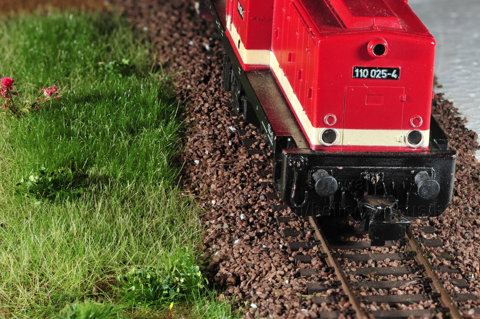
- a few weeds were then applied (miniNatur 725-22S) and a flower (miniNatur 998-26S)

This was how half of the board was made, the other one, as the photo shows, remained empty at the time. It was recently done, including the addition of a shrub, and, after the ties are further treated and some more weeds are planted, a new post will cover it in detail.

duminică, 26 decembrie 2010

Beyond Foam

I know this post was supposed to be about the test board & how it was build, but there's a good reason why this is being slightly delayed - a couple of trees just came in ! Actually a new order arrived a couple of days ago, not because I wanted so, but the guys at LokShop decided it was time to ship all the items already in stock (even though this accounted for only half of the total products ordered; maybe it's company policy - don't let the modeller down on Christmas no matter what). Anyway, along with the trees made their way, among others: a couple of Marklin bridge ramps, a Lenz DCC inverter, some PIKO replacement wheels, a couple of Noch tunnel portals, a few Woodland Scenics rock molds and a Brawa freight car. So I'm right now I'm thinking Brawa car + test board + one tree for the next photo shooting.
But getting back to the actual layout, there's one last piece of track that needs to be done in order to close the "loop" - the overpass bridge between the two tea cans. For this I got a couple of Marklin 74613 bridge ramps, and even though they are 360 mm in radius, I think I'll be able to keep the 380 mm radius from my plan. These come with hand rails and walkways on each side of the track; also the rivets are nicely done and the fixing system seems very sturdy. The one placed on the track is not equipped with these, while the other one placed on the foam is. The whole foam area is going to be elevated in the form of a hilly/mountaineous region, so the pre-tunnel track will look like it's carved its way through the landscape. For the overpass section a total of 3 ramps will be needed (it appears i won't be able to get away with just 2, as I originally thought). Of course such a long span cannot sustain itself, so an extra support it's going to be needed in the middle. And since the corresponding Marklin piers are out of the question (big bulky masonry piers), I think I will go with the new Noch girder structure. The problem with all the new laser-cut bridge kits from Noch is that they have been delayed ever since July. A nice lady from Noch assured me that they are going to be available starting this December, but so far none has made it in the "In stock" area in my LokShop account.
At the bottom the Noch portal is visible; it's facing the other way, since the tunnel masts will obviously be inside the tunnel.

miercuri, 1 decembrie 2010

Scenery Tests

Made a small test board about 2 weeks ago, to see how everything would come together - track, ballast and scenery. Just one side of the track has been constructed, while on the other the bare foam is visible; however it should be filled once I analyze the first half and realize what should be further tweaked.
But the real star was the imaging work done by a friend with pro- photographing gear and skills. The detail obtained is simply amazing.
In the next post I'll detail the materials used and post more photos.

duminică, 14 noiembrie 2010

Switch installed on SR

Not so much progress since the last entry, with only the Tillig EW2 switch mounted towards the end of SR segment. A small thing i've noticed is the change in the Tillig 86112 slow motion motors: if the first motor bought and installed about a year ago makes quite some noise, the newer ones, namely some bought a couple of months ago and the most recent ones, just a little over a month, are a lot quiter, with the last ones being the best, as they sound more like the prototype. I have no idea what causes this, and certainly is not the color of the casing, that first was black, and now, with the last 3 motors bought, seems to have turned to brown, but I'm going to contact Tillig, maybe there's an answer there.
The Lenz spare parts, as in the problematic wheels, didn't arrive after all, because the packet was returned back to Germany, the reason - a bad address. But I'm already used to it, since it's not the first time that this happened (Lokshop's full box of products being returned because of a can banned to see the inside of a plane is still fresh in my mind). So hopefully, yet again, this week the wheels might arrive, and who knows, maybe they'll fix the problem.
The last order to Lokshop - mainly rock molds and dedicated materials and the Brawa V100 loco - has half of its products in back order for about 3 weeks now, so I'm thinking about what to get next, so with a bit of luck I'll have new toys for Christmas. This only enforces the last rule i've discovered about model trains - if you think you might need something, order it with one month ahead the time you think you are going to actually use it.
A bit of zip texturing was tested, as described in the Sep/Oct 2010 issue of the Model Railroad Hobbyist magazine; which by the way is a very nich thing, and the price is - as the cover states - forever free. You can download it right from there site, in a variety of formats. After a bad start, trying to use water based pigments on plaster (with disastreous results), I ordered some proper
dry pigments and started experimenting. And until so far I cannot duplicate the 1:8 or 1:10 pigment to plaster formulas discussed by Joe Fugate, the guy that wrote the article. Maybe my pigments aren't that strong, or maybe there's something about the plaster I'm using. The ratio succesfully tested so far is 1:3, but I'm not so happy with the color, which looks washed, but adding more pigment and keeping the plaster quantity constant makes things worse, since the whole stuff won't "glue" anymore to the foam test patches.
The last photo shows the installed switch and most of the wires connected. Up next is testing that the motor can be unscrewed from this position (I didn't drill another hole through the foam+wood board since there are already quite a few) and connecting this switch to the existing SR track that's already glued.

duminică, 31 octombrie 2010

PT segment track status: complete

Finally the track on the PT (pre-tunnel) segment it's glued and electrically interconnected. It took quite some time because of the many little things that had to be done/fixed:
-various feeders had to be extended, since the original size was too short and they couldn't reach the space underneath the switch motors, were they're supposed to connect
- a couple of sections of track already cut to size had to be readjusted, because the original dimensioning wasn't done with one end firmly connected to the next piece of track, but rather simultaneously on both sides, hence small errors; but just an extra 1 mm in flex track length becomes a large problem since the track starts to buckle
- holes were drilled through the plywood for the PT switch pair
- the holders for the switches/switch motors on the PT segment had to be further tweaked, since the original versions were built just to get them up and running, but they couldn't properly sustain a train going over; so for the 3 switches on PT, a new plywood piece was glued next to the existing one holding the motor in place, and then different strip(s) of plywood were glued on the surface securing everything to the big foam board; for the first switch in the pair a foam holder was glued underneath the ballast piece since it was a better approach
- extra care was needed to avoid any kinks in the track pieces connecting to the switches, so pins and more pins and pins without the head were used
- for the second switch in the PT pair, the end of the remaining point blade also had to be extended since it wasn't staying in the tie plate, and with everything glued it gets pretty complicated to further modify the switch (the other point blade was extended here: http://piko-modellbahnen.blogspot.com/2010/08/test-driving-through-pt.html); the same old method was used, with 3 stranded wires soldered together forming the "extension", and this soldered to the tip of the point blade (originally i tried to solder on the outside of the blade, but the switch wouldn't go all the way through, so i used a small file to clean the solder and redo the same thing on the other side of the blade)
- a strange issue persisted with the (same) second switch in the PT pair - all the length of the switch is placed on a constant ramp, but the last portion (right over the switch motor) was level, which looked peculiar; all the various foam pieces - unglued yet -were measured and found to be the correct size, the switch itself wasn't bent and anyway it is rather flexible vertically, even in its foam ballast, so the only explanation could be that the big foam board was thinner in that exact spot; the fix was to use a strip of 1mm beneath all the supporting structures in this area as to "bump" the height
- the movement of the point blades on the first switch in the pair wasn't right in one direction; it seemed like the point blades would stall for a moment in one direction of movement; a little filling on a tie support causing this fixed it
- all 3 motors on the PT were unmounted, then remounted to test the access through the plywood holes; first the screw holding the actuating wire is loosened using a small enough ratchet that fits in the underneath hole, the actuating wire is removed from the mechanism, the 2 screws securing the motor to its plywood base are unscrewed and the motor then comes off; when remounting the screw for the actuating wire needs to be tightened a bit, otherwise the ratchet will not work, and the motor will have to be removed again to access this screw.

All the testing this weekend was done using the PIKO BR 01.5, since the Lenz BR 66 developed a small problem with one of its small rear wheels - namely a 'tick' every one revolution. I couldn't figure out exactly what causes it, so I mailed Lenz the exact problem, and they're sending a new type of wheels. Hopefully in about 2 days they'll arrive. As for the PIKO loco, I've spent quite some time with the desk lamp studying if the flanges touch the tie plates of the Tillig code 83 track, and couldn't come to a definite decision. However, after this weekend operating sessions, comparing the tie plates to their original state, several bumps on the plates seem to be a little shiny, a sign that sometimes the flanges do make contact. I'm looking into buying replacement wheels for the tender, since 2 of the motor wheels are located here and also because the difference in pulling power on the new Tillig track vs the old thick PIKO track profile is dramatic - the loco barely pulls itself on the new track. And it's definitely not because of any oily debris on the traction tires, since these were cleaned properly.


The photos: 1. final preparations before glueing the switches in place; 2. glueing the track under (proper) weights

marți, 19 octombrie 2010

LR track in place


The last piece of track needed for the LR was trimmed to size, all the right superelevated ballast foam pieces have been prepared, glue has been applied and right now it's all left to dry overnight.
An important thing i've observed tonight is how the Tillig joiners must be tight for glueing 2 adjacent pieces of curved track - the first pair used was kind of loose,and the kink was obvious. After changing them, everything got better, with the kink gone and half of the pins pinning the track down becoming useless.
Opinions about soldering the track are shared, but i choose not to solder because of 2 reasons: it doesn't look good from the examples i saw on the net and second, the track, just like the prototype, needs gaps at the end of each piece in order to contract/expand during periods of cold/warm weather. Soldering is however done on each piece of track, but to feeders. Actually this is how the old Piko track was done - with each sectional piece electrically connected to its neighbour by two thin fires placed under the ties. A bus will not be used for the current, since the original block scheme done for DC mode meant that for about 2 metres of track there was a separate pair of wires that fed it directly, this will be used, but now thwy will all carry the same DCC signal.

duminică, 10 octombrie 2010

LR continued

The order finally came, and with it the switch that was needed to carry on construction on the LR - a Tillig 85314. It got the standard 3-coat airbrushing, along with 2 other switches (Tillig 85323). And since i found setting up of the switch and attaching the motor rather complicated, considering i've done 4 previous switches, i made a small procedure that beside the initial step of painting the switches goes like this:
- build the plywood that will support the motor and drill holes for the screws (2); drill a hole for the rod that will move the points
- drill a hole through the ballast (the one corresponding to the switch model - without the specific model the switch doesn't stay right !) in 3 places - corresponding to the feeders on internal/external point blade and one that sets the polarity on the frog
- cut the right path in the ballast for the rod that will move the points
- with switch mounted in its corresponding ballast piece and the motor attached to the plywood piece right under the switch - with the switch in one of the two positions (not anywhere between) - the postion of the ballast on the plywood is marked
- if the tie holding the point blades tends to "slip" under its place right beneath the track, thus causing the motor to block when trying to move, then a little piece of plastic, cut from the material holding the tie plates together in tie strip, is placed transversal to the tie holding the point blades' direction; this problem can happen because of the turned tips of the point blades that are not long enough - however the tips should not be secured firmly to the tie holding them, because this will prevent a smooth transition of the blades when the motor is operating
- the shoes in the motor are ajdusted so the correct distance to the other position of the switch is right (actually just the 2 shoes controlling movement to the other position)
- the spots on the track where feeders will be soldered must be cleaned properly - using a bistoury to remove any oxide, using different patterns of movement - not just left-right, because this will not remove all the oxide; then the feeders are soldered
- electrical connectivity between the right blades must be checked, to ensure that no damage was done to the conductive elements placed on the back of the switch.

Last week holes in the big wooden board were made for the switch on the bottom of the LR segment, and for the switch on PT right next to the tunnel. Also the switch on the top of LR was finally glued to position, and so was the one on the bottom of LR. The LR ramp has been completely glued (the red books are keeping everything together in this operation on the first photo). All the electrical connections were also done for the mentioned switches. Part of the line that makes the LR was glued to position, along with superelevated ballast: the difference in height is 1 mm, which is prototipically correct (on real railroads the height of the outer rail above the inner rail , also named cant, can have values of 100mm).
In preparation of the Gras Master tests, some dry pigments were also ordered (second photo). Got these from a local retailer, and along with plaster, these are used in a technique called zip texturing, whose main objective is to produce realistic dirt.
Also a couple of old wheels were changed, since the damage was so hard that there was no other way (mainly because of handling them with the hands as a kid led to exfoliation of the material (chrom maybe?) coating the wheels).
But the real shocker was the Gras Master + Silflor (or miniNatur, as they are sold in Europe). The result is just superb, and the 130 euros payed just for the GrasMaster are certainly worth it.