duminică, 9 februarie 2014

Precision Scale

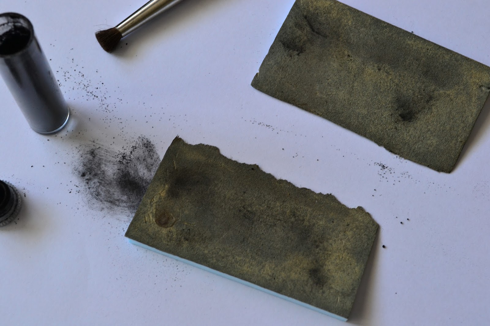
Even though I've revisited the earth formula here, I never really managed to make a true "formula" - one that could be replicated time after time, using precise measurement. As a result the various earth patches done so far on the layout vary in various degrees. Since I've been having a hard time matching colors with different batches lately, I've decided it's time to take things further and bought a precision scale. It can measure in increments as small as 1 milligram, so hopefully this will be good enough to replicate various dry pigment formulas over and over again. At 20 pounds, it's actually a good price - considering it actually has that 1 mg granularity observed after some testing. The photo shows this little device at work, while I was adding small amounts of ultramarine blue to the old earth formula (5 parts plaster, 1/5 parts burnt sienna, 4/5 orange). This has to do with a small test board made from a piece of foam and a sheet of plaster cloth applied on top - its role being that of sampling various combinations and writing down the various ratios involved. 
Why blue pigment instead of pure black one to make the formula slightly darker ? 2 reasons: the complementary color of the light brown-ish color that my earth formula has is actually blue, as seen here (a hue plus its complementary color will yield black in color theory when applied to pigments as stated here), secondly, I've never experienced this combination before (I've been adding only black pigment until now).

sâmbătă, 27 iulie 2013

Finished Brawa Platform

First described here, the Brawa platform is now almost completed - first 2 photos show the status captured minutes ago. The asphalt cracks are partially filled with some winter miniNatur static grass, probably some autumn model will be added too.For asphalt, a hard foam was used (photo 3) - this has been originally used to package the Noch tunnel lining and came quite handy now. Various cracks and dents were applied, to simulate as closely the real surface. The color was obtained as follows: first, all was painted with Woodland Scenics (WS) Stone Gray; after this dried a series of washes was applied, only after the previous one completely dried, in order: 1:8 WS Concrete, 1:8 WS Burnt Umber, 1:8 WS Yellow Ochre, 1:3 WS Stone Gray (as opposed to the rest, this was applied perpendicular to the length of the platform), 1:8 WS Yellow Ochre. After the first yellow wash, some Noch black weathering powder was used to break the monotony - even if this looked too powerful at first, the subsequent washes toned it down just right.
After painting, the soldering gun was used (photo 4) to take away from the edge, so that it will bind correctly with the platform edge which was already fixed. The groove of the thermocutter was used to hold the foam in place. 2 supports were made from regular foam in order to support the platform once fixed (photo 5), after which it was glued, with the same Woodland Scenics color containers that were previously used for washes pressing down (photo 6). The angled platform ends were painted in the same way, then fixed.


Hints


Over the time, I've been compiling quite a list of small notes, consisting of small hints and some activities that should eventually make it to the plans for each section of the model railway. Since every time I run into the pile I keep reading the same things - I've decided it's time to put the hints somewhere, and the activities to their respective plans. Hints are centralized below.

 1) When unmounting a point switch, it's more easier to simply gently lift the tile where the motor rod connects (2nd photo) - like this there's no need to go underneath and unscrew the "cheese" screw that clamps the rod to the point motor mechanism. If not doing this too often, the hole in the plastic tie shouldn't get larger in time
2) The plaster cloth "lids" should have a non-uniform contour, so one cannot easily spot the difference in height
3) To provide access to various wires underneath the terrain, buildings with removable roofs can be placed on that spot
4) A landmark for plaster cloth "lids" can be achieved by gluing specific plants on the terrain supporting it, so when the lid must be placed on the layout, there's no doubt about its final position
 5) The Noch glue, used for the static grass, is diluted 1:2 glue to water, so the there's no visible difference in the terrain color after this dries, especially at the "border" zone between the original terrain and the one that was soaked
6) The static grass should be pressed down lightly next to a figurine or on paths where there's supposed to be traffic
7) On areas where a plaster cloth "lid" will be applied next to a segment of track, there should be a minimum of 3-4 cm sideways from the foam support underneath the track - this will allow the edge of the lid to sit over the terrain, but not to close to the track itself (where ballast usually lies - making "hiding" difficult)

8) For the switch connecting segments D with C/SR, the "cheese" screw can be accessed with a long screwdriver, as seen

in the 3rd photo
9) For the same switch, removing the Tilling 86112 can be done using a mirror, placed like in the 4th photo, and using a curved screwdriver for the 2 screws holding it in place
10) The mobile rod for a switch motor can be easily removed if the point is brought into a "half-switched" position - this can be easily achieved by turning off the power for the switch motor, modifying the Phidget controller, then powering on briefly so the motor doesn't do the complete lap

marți, 23 iulie 2013

Artitec Oil Cart

Got a new order last month from LokShop that also contained an Artitec oil cart. Looks like Artitec is suggesting 2 color schemes - one with a bright orange for the barrel, the other, more natural, sporting a grey mettalic finish - as seen here. I opted for the latter. First photo is the small original package. Same as with the Artitec lantern building, the burrs need to be removed, this time using a combination of file and cutter. The second one shows the elements to be painted black - the chassy, supporting brackets, the wheel axle and the already masked (with 3M Vinyl Tape 471+) barrel. Last photo shows the progress over the parts to be painted in a wooden color - Tamiya Desert Yellow (XF-59) was used in 3 layers. Next up will be the piece that resembles a set of small oil canisters, located in the back of the cart itself, and finally the metallic parts - the barrel and the metal band on the wheels. Finally drybrushing along with some weathering will be used to finish it.


sâmbătă, 8 iunie 2013

Switch Issues

Soon after fixing the problem described here, I was worried that the same issue happened to one of the switches in the PT pair (M31), which experienced the same symptoms of poor electrical connectivity when part of the locomotive wheels were in the frog. Turns out it was only the Tillig 86112's brown wire that came loose from its connection with one of the wires providing power. When this happens, the voltage measured between any point of the frog and its opposing rail will be at about 6-7 Volts.
With this out of the way, I turned my attention to the switch in front of the tunnel, which started making a powerful noise for quite some time now. Opening the switch, cleaning it with the airbrush (blowing just air) and removing part of the components indicated that the motor was not at fault, and the cause of the noise was actually a broken cog - the hairline crack is visible in the first photo - not something that bad, but big enough to make the gap between those 2 teeth generate a considerable noise when being driven by the motor's worm drive. The whole component is present in figure 2. Luckily some time ago I've ordered a spare 86112, so the fastest way to fix the problem was simply switching the whole rod that contained the broken cog. Comparing the 2 switches (photo 3) showed no visible difference in this, but contrary to my memory, it's not just the color that was different among the first switch drives I bought and the subsequent ones - actually the motor itself is changed, and comparing the sounds one can immediately notice that the new ones are far more quieter. After everything was reassembled on the old drive and small amounts of silicone grease applied, I've placed the old rod and the components of the new drive (that interact with the rod) in one of those dynamic-compartment types of small plastic boxes, one of which I bought today.


duminică, 2 iunie 2013

Electrical Observations

Got curious today about how much current is being drawn by the whole layout, so I've made a quick measurement and noticed a rather high consumption: about 400 mAmps with one light signal, the Viessmann pickax figurine and the Brawa V100 idling.
I went ahead and opened the box seen in the photo to try and see what wire goes where. Since 2 sets of wires were connected using the thing which can be seen next to the measurement device's black connector, I decided to switch to using the Viessmann devices specifically built for this (the yellow one in the center with its adjoining connectors). This way the wires could be disentangled and tags were placed on each fire or pair of wires, depending on the case. Now with the ability to disconnect/connect everything one by one, the results became clear:
- LZV100 draws 160 mAps, with or without the output to the lines connected (rather important, since in the beginning I though there maybe were losses on the rails themselves, even though feeder wires are soldered to each rail segment) - in the photo this is the black box in the lower left corner of the cardboard box
- the LK200 inverter didn't consume anything (no locomotive was ran on its segment though) - in the photo it's the small white device on top of the LZV100
- Viessmann 5223, the module that commands the 4013 Viessmann light-signal, consumes 80 mAmps
- the 4013 light signal consumes 20 mAmps (this includes its entries connected in cascade to the Phidget for obtaining the multiple aspects this signal is capable of)
- the pickax Viessmann figurine draws 30 mAmps
- Brawa V100 consumes 40 mAmps while in standby, 20 mAmps for the lights and 150 mAmps for the sound (when the sound effects aren't that noisy the value seems to go down)

Fixing Electrical Connectivity on the Long LR Switch

There have been some electrical problems for some time now, with the Brawa V100 going through this long switch, whose installation was covered here. When the locomotive would be going slow, in the position marked by the two red pins, it will lose power. Using an electrical measuring tool soon showed that the frog rails weren't receiving any power (the frog rails are the fixed rails that go "out" of the frog).
Fixing it would have been possible using Tillig's 85506 contact clips, but as with the rail joiners, electrical conductivity isn't that reliable. Only thing that would make sure the original issue goes away was soldering a wire to the frog rails.
Un-mounting the switch however wasn't that easy, since the rail joiners only slided completely at the upper end (by pushing the ties a bit; even if secured to the foam, the latter allowed just enough movement). For the other 2 ends -since 2 isolating Tillig joiners are used for the 2 frog rails, the rails had to be physically lifted to allow removal. Alcohol was used, using a pipette so that the drops could reach between the ties. After a few applications and a couple more minutes, the ties came loose and the switch lifted from its support.
In the second photo the cause of the problems can be seen: the metal piece joining both the frog rails (now soldered to the red wire) and rails inside the frog itself (now soldered to the brown wire; also it's clearly visible where these end, before the point blades themselves start) was secured in a faulty manner when this switch was build - resulting in poor connectivity. Cleaning of the metal spots and the soldering itself was done as mentioned in the article at the beginning. Even though the original problem consisted of the frog rails lacking electrical connectivity, I went ahead and soldered a wire to the frog itself, so this all this removal operation won't be needed in the future. Even if first decided to remove the violet wire soldered to the metal piece, I re-soldered it thinking that there's no harm in an extra point of contact.
All 3 wires were connected to the Tillig's 86112 white wire. The third photo shows how the switch looks like installed in its place. Some ballast must be glued so that the remaining holes can be hidden, and also some weathering powders to make the soldered wires invisible

The way the wires are connected together under the board is presented below for future reference:
I - blue, green, green, violet (the latter is the wire secured to blade associated with the inner route)
II - brown, yellow, yellow, blue(the latter is the wire secured to the blade associated with the outer route)

The rod connecting to sliding tie to the Tillig motor was cut to size also. One important warning is to secure the screw holding the rod, otherwise symptoms like the ones mentioned here can appear.


A very good guide for assembling the Tillig switch kits can be found here.