duminică, 24 august 2014

Even More Electrics

Again there's been some work done exclusively on the wiring part. The original connecting board now has both its D-Sub connectors soldered to the corresponding wires (photo 1 showing work in progress). These wires consist mainly of individual signal LEDs and track / power / optical detector current. For the second connecting board, built a month back, the connector with the optical detector wires had about half of these soldered (photo 2 from when this was done). The short-term goal has become setting up 3 signals and the already connected optical detector in such a way that each signal "thinks" and reacts according to the various detectors located in front and after it.
This will most likely be a stepping stone towards the final computer-controlled code, yet should be simple enough to get some visible results fairly quick.
  Since the connector with the wires for optical detectors has been fixed to the connecting board, the control panel board had a corresponding connector installed, and wires placed for linking it to the Phidget 1018 interface. A second cable was assembled in order to link these 2 (photos 3 and 4).

  Finally the wiring plan for the layout itself has been entered in a Visio document (preview in photo 5). Holes cut in the foam underlying board are also present. The whole idea is to be able to successfully track a wire, since now there's information about its endpoints, its color and the tooltip entered (ShapeSheet->Comment). As for the control panel (preview in photo 6) - the wires that will be done in the future still have a black color, to differentiate from the ones already installed, that have been colored according to their real counter-parts.

  Tonight I've also connected the various power supplies and checked that everything works well. Last photo shows the temporary setup employed, complete with an USB hub, which was connected through 2 USB extender cables - just to be sure that the hub can be physically placed behind the layout - actually the spot where the control panel will be sitting, in a vertical position.
  What was unexpected was the sheer amount of time needed to complete this wiring part. Just tracking each and every cable on the layout itself and drawing the corresponding diagram took easily 30 work hours. Each 32-pin connector cable took more than 5 hours to build. What started as a very simple job ended taking much more that I would have ever expected - which makes me seriously think about DCC decoders for each signal, switch and other accessory in the future, given the wiring should mainly consist of 2 wires carrying the signals across. But for now - and this layout - things will stay the same. There are still a couple of  items to be purchased - namely some Phidget boards that will take care of additional optical detectors, switch feedback and switch operation; some D-Sub connectors; a small power supply for the optical detectors in order to stop using the current bulky one; and a few others.


duminică, 20 iulie 2014

More Electrics

Realized at one point that since there's no map of how each wire goes where, not to mention that some of the wires lost their purpose during the time since not all of them were marked - that it's gonna get complicated soon if this isn't rectified. So there have been quite a few hours over this months of mapping out what goes where. A Visio diagram was also employed, and each wire colored as it is on the layout, complete with tool-tip comments that show a wire's function when hovering over it.
Work was done to the electrical panel that will contain all the modules (Viessmann, Phidget, etc.) so I can finally move away from the wiring-in-a-box approach
Last but not least, since it turned out that quite a few wires will be required in the end, no less than 4 D-Sub connectors would be needed (37 pins/ connector, however because I'm using some 32-wire legacy cable, 5 of those pins will go unused). The required connectors, brackets and various other items were purchased;  so far a connecting cable was built, the original connecting board got modified so that it holds 2 connectors, and a new enclosure for a similar cassette plus the corresponding board were just finished today.


duminică, 9 martie 2014

Precision Earth Test Patches


As stated previously, the precision scale recently bought was instrumental in creating a test board, with 8 patches of earth formula. This is simply a 1-cm thick foam board, on top of which one sheet of plaster cloth was applied - both to provide better grip for the zip texturing to come, and to replicate exactly the layout structure. The starting formula was the now classic 5 parts plaster, 1/5 parts burnt sienna dry pigment, 4/5 orange dry pigment. Each patch has a known ratio of blue ultramarine pigment, which was increased  in small doses against each one. For each patch, the procedure was similar - wet the spot with white glue, apply the corresponding formula with a tea strainer, leave to dry for 1 hour, then repeat again in the same location, then move on.

  After adding the determined weight of blue ultramarine dry pigment - usually around 0.04 grams - the whole formula would be thoroughly mixed in a "shaker" for 4 minutes, as to ensure a uniform outcome (the days when I would use a spoon to mix things are long since gone - since applying the resulting mix resulted in particles of the stronger pigment - then black - "shining" through the whole formula).
  As the last patch on the first test board was still not matching the medium earth color on the layout, I decided to extend the batch of tests on another test board. Photos 2 and 3 show the first test board and second one, respectively. The white spots on the edges of the patches represent white glue, migrating from the patch under work to the previous one(s), already finished. Not a big drawback since the colors can be matched like this with no problem. The 2nd board still needs to have one application over the 7th patch, and the last one completed.

  For both boards, the order of the patches if left to right on the top row, then right to left on the bottom row - so that the 1st one is on top left, while the 8th one always on the bottom left. 
  The percentages of blue ultramarine dry pigment is as follows: 1st test board - patch 1: 0%, patch 2: 0.1%, patch 3: 0.22%, patch 4: 0.43%, patch 5: 0.61%, patch 6: 0.9%, patch 7: 1.2%, patch 8: 1.6%. 2nd test board -patch 1: 1.8%, patch 2: 2.0%, patch 3: 2.2%, patch 4: 2.5%, patch 5: 2.8%, patch 6: 3.1%, patch 7: 3.3%, patch 8: 3.5% (patch 8 not visible in the photo at this time).

The last photo shows both boards alongside, just to get an idea of the color ranges in both.

duminică, 9 februarie 2014

Precision Scale

Even though I've revisited the earth formula here, I never really managed to make a true "formula" - one that could be replicated time after time, using precise measurement. As a result the various earth patches done so far on the layout vary in various degrees. Since I've been having a hard time matching colors with different batches lately, I've decided it's time to take things further and bought a precision scale. It can measure in increments as small as 1 milligram, so hopefully this will be good enough to replicate various dry pigment formulas over and over again. At 20 pounds, it's actually a good price - considering it actually has that 1 mg granularity observed after some testing. The photo shows this little device at work, while I was adding small amounts of ultramarine blue to the old earth formula (5 parts plaster, 1/5 parts burnt sienna, 4/5 orange). This has to do with a small test board made from a piece of foam and a sheet of plaster cloth applied on top - its role being that of sampling various combinations and writing down the various ratios involved. 
Why blue pigment instead of pure black one to make the formula slightly darker ? 2 reasons: the complementary color of the light brown-ish color that my earth formula has is actually blue, as seen here (a hue plus its complementary color will yield black in color theory when applied to pigments as stated here), secondly, I've never experienced this combination before (I've been adding only black pigment until now).

sâmbătă, 27 iulie 2013

Finished Brawa Platform

First described here, the Brawa platform is now almost completed - first 2 photos show the status captured minutes ago. The asphalt cracks are partially filled with some winter miniNatur static grass, probably some autumn model will be added too.For asphalt, a hard foam was used (photo 3) - this has been originally used to package the Noch tunnel lining and came quite handy now. Various cracks and dents were applied, to simulate as closely the real surface. The color was obtained as follows: first, all was painted with Woodland Scenics (WS) Stone Gray; after this dried a series of washes was applied, only after the previous one completely dried, in order: 1:8 WS Concrete, 1:8 WS Burnt Umber, 1:8 WS Yellow Ochre, 1:3 WS Stone Gray (as opposed to the rest, this was applied perpendicular to the length of the platform), 1:8 WS Yellow Ochre. After the first yellow wash, some Noch black weathering powder was used to break the monotony - even if this looked too powerful at first, the subsequent washes toned it down just right.
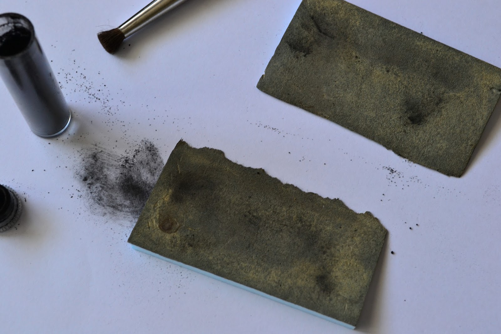
After painting, the soldering gun was used (photo 4) to take away from the edge, so that it will bind correctly with the platform edge which was already fixed. The groove of the thermocutter was used to hold the foam in place. 2 supports were made from regular foam in order to support the platform once fixed (photo 5), after which it was glued, with the same Woodland Scenics color containers that were previously used for washes pressing down (photo 6). The angled platform ends were painted in the same way, then fixed.


Hints


Over the time, I've been compiling quite a list of small notes, consisting of small hints and some activities that should eventually make it to the plans for each section of the model railway. Since every time I run into the pile I keep reading the same things - I've decided it's time to put the hints somewhere, and the activities to their respective plans. Hints are centralized below.

 1) When unmounting a point switch, it's more easier to simply gently lift the tile where the motor rod connects (2nd photo) - like this there's no need to go underneath and unscrew the "cheese" screw that clamps the rod to the point motor mechanism. If not doing this too often, the hole in the plastic tie shouldn't get larger in time
2) The plaster cloth "lids" should have a non-uniform contour, so one cannot easily spot the difference in height
3) To provide access to various wires underneath the terrain, buildings with removable roofs can be placed on that spot
4) A landmark for plaster cloth "lids" can be achieved by gluing specific plants on the terrain supporting it, so when the lid must be placed on the layout, there's no doubt about its final position
 5) The Noch glue, used for the static grass, is diluted 1:2 glue to water, so the there's no visible difference in the terrain color after this dries, especially at the "border" zone between the original terrain and the one that was soaked
6) The static grass should be pressed down lightly next to a figurine or on paths where there's supposed to be traffic
7) On areas where a plaster cloth "lid" will be applied next to a segment of track, there should be a minimum of 3-4 cm sideways from the foam support underneath the track - this will allow the edge of the lid to sit over the terrain, but not to close to the track itself (where ballast usually lies - making "hiding" difficult)

8) For the switch connecting segments D with C/SR, the "cheese" screw can be accessed with a long screwdriver, as seen

in the 3rd photo
9) For the same switch, removing the Tilling 86112 can be done using a mirror, placed like in the 4th photo, and using a curved screwdriver for the 2 screws holding it in place
10) The mobile rod for a switch motor can be easily removed if the point is brought into a "half-switched" position - this can be easily achieved by turning off the power for the switch motor, modifying the Phidget controller, then powering on briefly so the motor doesn't do the complete lap

marți, 23 iulie 2013

Artitec Oil Cart

Got a new order last month from LokShop that also contained an Artitec oil cart. Looks like Artitec is suggesting 2 color schemes - one with a bright orange for the barrel, the other, more natural, sporting a grey mettalic finish - as seen here. I opted for the latter. First photo is the small original package. Same as with the Artitec lantern building, the burrs need to be removed, this time using a combination of file and cutter. The second one shows the elements to be painted black - the chassy, supporting brackets, the wheel axle and the already masked (with 3M Vinyl Tape 471+) barrel. Last photo shows the progress over the parts to be painted in a wooden color - Tamiya Desert Yellow (XF-59) was used in 3 layers. Next up will be the piece that resembles a set of small oil canisters, located in the back of the cart itself, and finally the metallic parts - the barrel and the metal band on the wheels. Finally drybrushing along with some weathering will be used to finish it.