vineri, 30 noiembrie 2018

Mini-Test Test Boards

  As previously discussed, the test boards themselves will have to be assembled together in order to form a closed loop of track to be used, then disassembled when done to clear up space.
  When I really started thinking on how I would go about actually building the boards - around May this year - I didn't have a clear idea on how to go about it - neither connectors, structure, not even the material to be used. In fact even the material that was used as base for the existing layout is something that was bought by my dad since I was a kid. And 1980s in the country I grew up in - Romania - meant that communism won't really allow a large set of choices when it came down to wooden boards (the same limited set of choices were around the scarce quantity of food, too). So we ended up with some sort of MDF purchased one evening and carried across town by public bus. But fast forward to today, and being part of the civilized world means pretty much being able to get whatever you want, since there will be a retailer out there that sells it. What was left to do was go documenting on the Internet, which was bound to yield what the model railroading world deemed the best solution for what I was looking for.
  It turns out there are 2 clubs - FREMO in Europe and FREE-MO in US - that built their own comprehensive standard about modules for model railroading. A full PDF for the former can be found on this page, and for the latter here. Studying both gives plenty of data regarding which materials to use, how the end plates for the modules should look like (complete with drawings and dimensions), height of modules, ways of securing the modules together, event paint to be used.
  Let's start - for the material it's important to avoid dimensional lumber. This will warp in time. Instead plywood should be used, given the successive layers of wood fibers placed perpendicular to each. FREE-MO even goes as far as explicitly name birch plywood as the material of choice. Problem solved here.
  For the module's underlying framework itself, neither standard goes into great detail. I couldn't find much aside from how the end plates should look like. Nothing like L-girder or other type of detail. Turning to other sources - Miniatur Wunderland did document their initial process  of building the wooden framework, yet their exhibition is permanent, so not very much that could be used from there. Others, such as Mianne Benchwork, go into details (given they're selling the end product), but their method of connecting everything together is by cam lock and nut - which my initial tests didn't really indicate that the best thing for my needs. At this time I don't have a final picture of how the test boards will look like, but I'm getting closer.
  Another aspect is connecting the boards together. The FREMO standard mentions only using 8mm bolts to secure the boards together (inserted through 12mm holes), yet there's no precise instruction for what to use to align the boards. Half a millimeter misalignment at this scale means a big problem. More searching led to Vikas Chander's blog, that has a post handling building FREMO modules. In this post, he's showing the connectors used, and a link to the supplier that sourced it for him. Unfortunately the link is currently dead, but I managed to find a source for those exact things here, at rbs-modellbau. Went ahead and got 3 pairs of them in September, at about 8 EURs per pair. I continued my search for other types of connectors, and came across pattern makers dowels. An online shop that has them is railroomelectronics - the direct link is here. A pack of 2 pairs of these costs about 9 EUR, coming in at 4.5 EUR per pair. I've also ordered 2 packs in September. I also came across table-top alignment pins (a link here) but from what I understood they're less precise than the former 2 types above. I stopped here, and decided that the end goal is to analyze both types of connectors and choose the best.
  That's pretty much all the info I needed to go ahead and do a proof-of-concept consisting of 2 tiny modules, that could be connected and disconnected. I already had a board of 1x1 metres of 1.5mm thick birch plywood bought in July. For connecting the the various plywood pieces, I settled on using 8mm dowels. All that was left was doing a plan and actually build the thing. I quickly ditched the idea of drawing on paper - there would be a lot of erasing and redrawing involved -, and went ahead and looked for a software tool. On the RBS page that goes into detail about what they use, I saw "Inventor" as the 3D software. I found out it's something Autodesk has been building close to 20 years for now, and from the various Youtube videos, it looked like something I needed. So I learned the basics for Autodesk Inventor, and then eventually designed the mini-test boards/mini-modules.
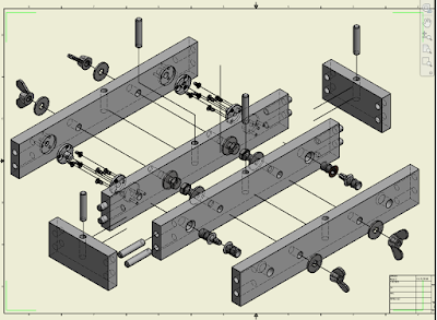
  Seen in the picture is the exploded view of the end result. The 2 long pieces in the centre - the ones closest together and the 2 small lateral ones form one mini-board, while the other 2 form another one. These outer 2 in fact form a similar mini-board as the first one, but are depicted here separated, as to highlight the connectors and how they fit together. The 2 mini-boards can thus be connected at will - either using one set of connectors, or the others. Note that the top of the 2 mini-boards is not shown in the diagram, as to not overload the plan. Click on the picture to zoom in.
  The connectors seen in the lower right (not the wingnuts on the far right, but those between the 2 long pieces) are the connectors supplied by RBS, while the ones in the top left are the pattern makers dowels ones.


duminică, 25 noiembrie 2018

Bosch PTA 2400

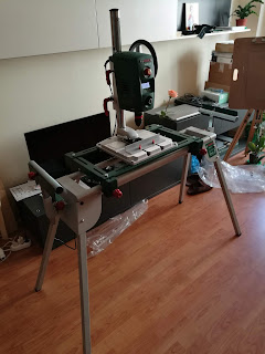
  As described in the last post, the Bosch PBD 40 has to rest on a solid base in order to use it properly. Though tests were initially performed by holding in place with only dumbbell weights (!) so it didn't tip over, a proper solution had to be found. And sure enough - Bosch provides yet another product just for this purpose - the Bosch PTA 2400. Though its main target - as in fixing to it - are the mitre saws, the PBD 40 is listed amongst the devices compatible as well. So at the beginning of this month I purchased one. It's really sturdy, and at a bit over 20 kg, there's no risk of the drill press - itself weighing 11 kg - to topple over. I've been using the drill press for the last 2 weeks almost daily, and the table is definitely worth the investment. Bonus - for the rather little apartment I currently reside in - the box it comes packaged in is rather compact.
  I'm posting the pictures taken during unboxing - they proved their worth when putting it back today for storing until the time for the next woodworking session comes.


Dedicated Test Track

  After working on the speedometer inner workings for the end of 2017 and spring of 2018, it become evident that once the readings of the speedometer were post-processed, any formulas found for the distance would have to be tested on real track. There are a number of reasons this is so:

  • Difference between rolling stands and real track - running on real track could provide slightly different results than the ones obtained from a roller stand
  • Effect on load - on a rolling stand the effect of pulling a load (eg multiple cars) cannot be studied. But on real track this can be easily seen
  • Value-collection differences for speedometer - the process of obtaining the data from the speedometers might be affected by several factors (eg wheel slippage against the speedometer) that could affect the outcome itself - the formulas. The real track would have to validate the formulas obtained as such

Using a section of the model layout, as done previously, is not the best way of moving forward. Repeatability of tests is not easily achievable on a section of the layout itself, nor can specific detectors be mounted at particular intervals. A dedicated test track becomes mandatory. Which entails building a series of boards in order to support that length of track.
  Initial thought went into how this test layout should look like, in order to support measuring the stopping distance automatically between runs. The end result involved a length of about 3m, and a width of a bit over 1m. Since this length cannot be accommodated by a single board - since it will become impossible to move this ever, nor would the current space permit it - the whole structure would have to be built in sections, that can be assembled together and disassembled for storing.
  Realizing I had practically no tools for doing any precision woodworking in the current place I live in, in the beginning of June this year I went ahead and purchased a column drill press - the Bosch PBD 40. This was followed at the end of the month by a table saw - Bosch PTS 10 (the link is in German, couldn't find one in English). I quickly discovered that the PBD 40 - although can be rotated so that it drills into longer pieces of wood - needs a sturdy base. What was purchased next ? The next post will detail it.

Speedometers

Since initial attempts at getting the real-time speed for a locomotive as this decelerates and comes to a stop proved cumbersome (to say at least), I've looked around to see if anyone manufactures devices for reading the instant speed of a locomotive - and more importantly - sends this info to the PC. Sure enough, I found Bachrus, which were doing this for quite a while.
I've went ahead and ordered 2 such speedometers - which are really just regular elements of a classic roller stand with a mechanism to relay the wheel speed to a PC, along with some other "saddles" for placing the rest of the wheels. The first photo shows 2 regular saddles under the left bogie of the Brawa V100 and 2 speedometers on the right bogie - easily identified by a red wheel each - positioned in opposite directions so they can successfully fit on the same bogie. The purchase of all the kits was done in August 2017. 
   Unfortunately, while writing this post, and not understanding why their website isn't reachable any longer, it appears that the company owner - which was kind enough to provide technical details over email at the time - has since retired, and as such the website and Youtube channel no longer work as of today (Nov 2018). Nonetheless, the link above contains a pointer to an archive of the website as it was back when it was up.

  Back to the speedometer itself - the way it works is similar to the old ball mouse. The red wheel of the speedometer is connected by a shaft to the black wheel with "slits" - as seen in the 2nd photo. These "slits"either let - or prevent - light from a LED hit an optical detector located across. This can be seen very well in the 3rd photo, showing the same black wheel as before mounted in its place, where the enclosing "chair" - soldered to the green PCB - has a pair of LED emitter and detector that end up resting on each side of the wheel. The wire seen leading from the edge of the enclosing is connected to an interface (photo 4) by means of an audio jack. The other end of the interface is connected to a standard USB cable, which is then hooked to a computer.


  I've spent quite some time understanding how the device works internally. The technical data received from Bachrus - as mentioned above - pointed me in the right direction. I needed this in order to understand when are the speed values sent across the wire, and also to know the expected accuracy of the device. Keeping the nitty gritty details out for now, the speedometer counts the time it takes for a "slit" to pass in front of the optical detector. The "counting" is done using a timer clocked at 1.5 MHz, powered by a PIC18F13K50 microcontroller inside the interface (the black box saying "MTS-DCC"). Once the "slit" has passed, the timer is stopped and the value noted. The interface averages 4 such consecutive counter values, and sends the value across the USB cable to the PC.


  As for the accuracy of the device - there's nothing mechanical I had at hand that would come close to rotating with a constant speed. A locomotive - although on track seems to be cruising at the same exact speed - is shown by the speedometer to vary its instantaneous speed quite significantly. The next best thing was "simulating" a perfectly constant rotating black "slit" wheel. How ? By tricking the interface into believing it's receiving signals from the speedometer, when in fact an emulator circuit is generating specifically crafted electrical signals, timed very accurately. This was done using the AWG (Arbitrary Waveform Generator) module of a PC-based oscilloscope (Picoscope 2206B) - purchased specifically for this - and a couple of electronic components on a breadboard. The results were quite impressive - just take a look at the chart below. In this particular instance the hardware setup was configured to simulate a constant speed by generating pulses every 0.5 milliseconds. The horizontal axis shows the actual time values measured, while the vertical axis shows the number of instances encountered for each time value. Summing the number of values within +/-1 microsecond of the target 0.5 milliseconds, this represents 99.947% of all the values. Therefore at least the electrical part of the speedometer is pretty exact. Provided there's no wheel slippage from the locomotive while running across the red wheel of the speedometer, the values measured should be pretty exact.

  As for the formula for the instant speed, and the speed variance measured for the locomotives tested, this will be treated in a future post. Otherwise this introductory post would become quite extensive.

Update 1/5/2020: Bachrus has since closed down. The specification that was provided to me back when I wrote this post is here.


duminică, 18 noiembrie 2018

It's (not) About Time !

It's been quite a while since the last post. Quite a few things happened - despite no activity here - including moving to a new place 2 years ago, purchasing various wood-working equipment, buying a PC oscilloscope and attending my first Nuremberg toy fair, just to mention a few.
The layout I was working on is still accessible, and the plan is to eventually finish it, however for now the focus is continuing the work concerning deceleration. Continuing where I left off the last time, right after obtaining a formula for the approximate deceleration time for the ESU v3.5 decoder, used in their Brawa V100 locomotive, the problem is that just knowing this piece of information isn't enough to determine the length of track the locomotive will travel while decelerating until standstill.
This can be easily seen through a quick example. Click on the picture to enlarge the sample. There are 2 charts representing instant speed (s) versus time (t), taken for 2 different decelerating objects. Both objects are travelling at a constant speed 3 for the first 3 time units, before starting deceleration at t=3. They all reach standstill at t=7. The first one has a more "smooth" speed curve, going through intermediate steps before hitting 0, while the second one cycles abruptly from speed 3 to 1 at t=4. Computing the distance travelled yields 17 (3x3 + 3x1 + 2x2 +1) for the first object, and 15 (3x3 + 3x1 + 3x1) for the second one. Therefore despite taking the same time to decelerate (4 time units), the distance travelled is not the same.
Knowing that obtaining the distance travelled will be needed as well, I got to work in September 2016 trying to get the required data. A tripod (Manfrotto MK055XPRO3-BHQ2) was bought along with a slider (Dynaphos GT-M80) for taking overhead shots of the V100 and the exact position where it would stop following a deceleration. Since the instant speed is needed as well, the DSLR camera was turned to video mode - and a tradeoff between frame rate (the higher the better) and resolution (if too low, the precise position of the locomotive can't be determined; if too high, the frame rate drops). Since the camera couldn't physically "track" the locomotive in real-time, optical corrections had to be computed and the results adjusted. Why ? Looking from right above the locomotive's end and measuring its position on a track-side ruler - just as seen in the photo nearby - will result in a very different reading than if the camera moves 5 cm to the side (go on, give it a try). Next, the captured videos had to be analyzed - frame by frame - to get the position of the locomotive at each step, apply the corresponding optical correction, and compute an approximation of the instant speed. Not a lot of fun, considering that processing a movie would take about 2h.
How to get the instant speed in a more human way ? The next post will show the way.